
You wouldn’t steal a SAXS machine… Because you can print one! For the last few weeks, I have been playing around with a new little 3D printer in my lab. This one can print structures in ABS plastic, so I thought it would at least be useful for sample holders. Then I started experimenting a bit more…
[ed: you can enlarge any image by clicking on it]
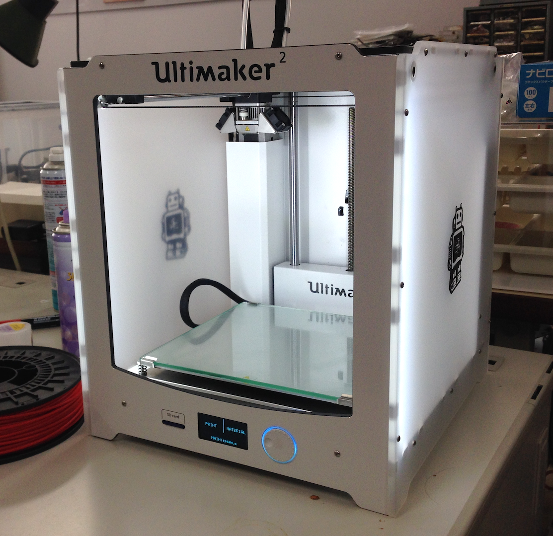
The printer in question is an Ultimaker 2 (Figure 1). This is a (Dutch) printer with good reviews and good specifications, and allows the use of non-proprietary plastics. Maximum print size is about 200 mm^3, and maximum resolution is about 25 microns (though typical, normal speed resolution is about 100 micron). This one retails for about 2 kEuro.
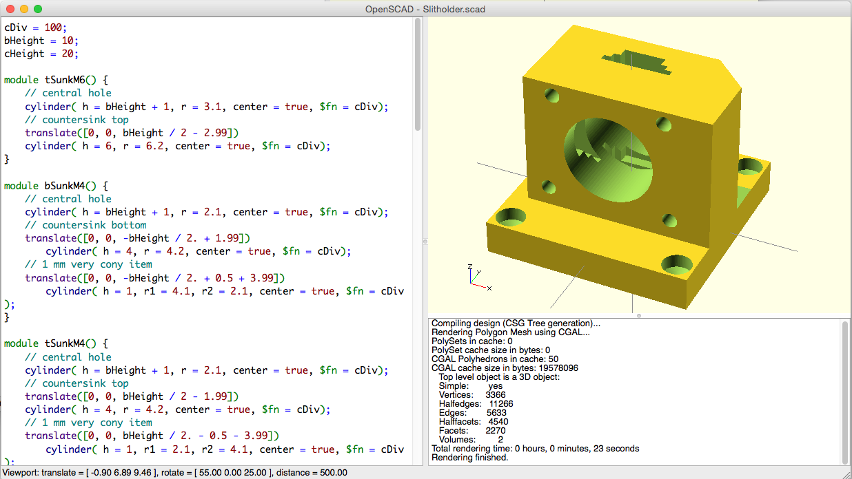
It allows me to design components in a wide variety of 3D drawing programs, so — because I am familiar with the programmatical 3D construction of POV-Ray — I chose openSCAD (Figure 2). This then outputs to one of the standard 3D formats (such as STL). This is subsequently read by the Ultimaker software, which converts it to G-Code suitable for the printer.
Printing initially was not so successful as the parts kept detaching from the work surface (after which they will move together with the nozzle to create a nice blob of plastic). After googling the question, I read that hairspray could be a solution. So I went for the extra-strong, cheap, unperfumed hairspray which solved all my sticky problems. Best of all, the hairspray sticks when the work surface is hot, but when the surface cools down, the item detaches nicely.
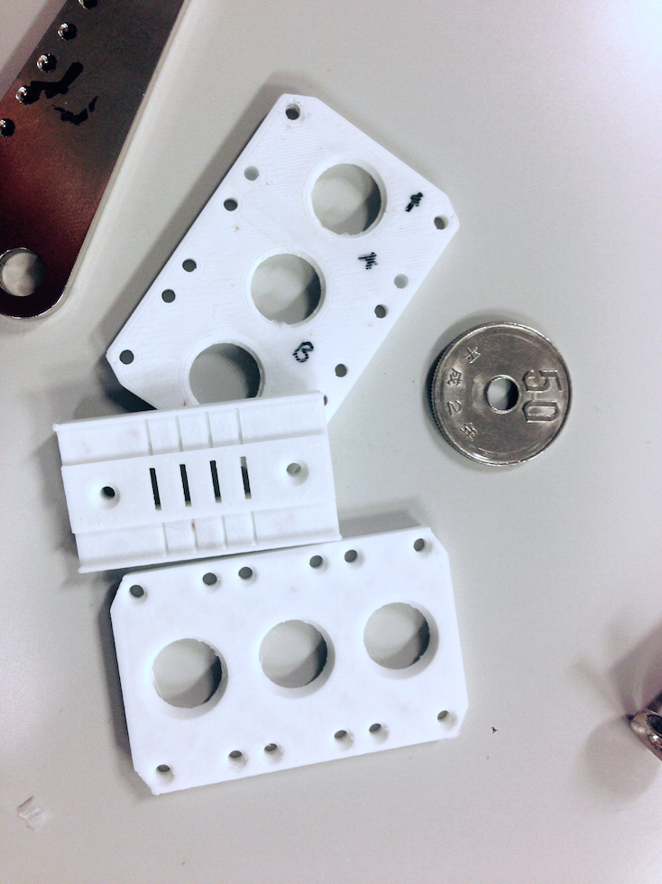
After printing a few sample holders for capillaries and disc-shaped samples (see Figure 3), it was time for more serious tests.
As you know from previous posts, I am in the middle of upgrading the Ultra-SAXS machine. This machine is going to get a new source soon, so I also took the opportunity to redesign it a bit to make it more convenient to use. Firstly, I want both horizontal and vertical collimation this time, with XZ-translation stages for alignment (the previous version only had one-dimensional collimation and translation).
This meant that I have new translation stages, and I needed new collimator holders (I nicked quite a few slit collimators off some discarded JEOL and Rigaku instruments). Furthermore, these components always need to be fixed to each other typically using adapter plates, plates with a few countersunk holes in them to bolt through. Making these from metal is a pain in the donkey, and very unsatisfactory (after all, it is just a square plate with some holes). I also needed posts to raise the items to approximately the right height.

So after a bit of designing, I spent two weeks printing (fortunately, I can print more than one component at once, as shown in Figure 4), after which I had a box full of printed parts! To give you an idea of time required: the components in Figure 4 took 22 hours to print.
When bolting the items together, I still ran into one or two problems. One of the posts had a slightly bulging top (which I should have sanded flat a bit), which upon over-tightening of the connecting bolts meant that I cracked some of the printed layers a little. Fortunately, I can now strengthen the design easily, and run another print. This makes it a lot less stressful and frustrating to design and put together, as the effort to make the components is much milder.
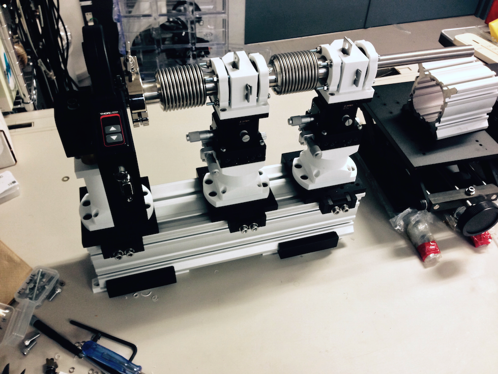
The finished collimation section (Figures 5 and 6), is in my opinion a great improvement over the previous one. What remains is to test the sturdiness of the set-up and improve the design of one or two of the components. After this, I can move on to the redesign of the next section: the two Bonse Hart crystal stages. Unlike the previous cool but cumbersome design, I will now separate the two rotations to allow for easy movement of either stage (greatly simplifying the alignment procedure). Once that is done, I will post on this topic once more.

One additional note is that the current slit holders are not vacuum tight. However, the ABS plastic used should be capable of withstanding vacuum. Redesigning the slit holders to allow for evacuation of the collimation section could be another point of improvement.
For now, I am very excited with the speed of development using the 3D printer, and I would highly recommend its use for rapid prototyping and manufacturing (and perhaps to print the occasional toy for the toddler). Who knows, maybe in ten years we will just print the latest SAXS machine!
Hi Brian,
very nice work !
I hope that 3D printer will help you to develop the instrument. I will start a project in the same spirit with my students next week, we will try to build a kind of light scattering experiments…
Keep us informed about the project progress.
Cheers.
Greg
Hi Greg,
Great minds think alike! Good to hear you are also working along a similar vein. I read that ABS can be a bit hygroscopic, so I need to do some tests to see if it grows/shrinks much when it absorbes moisture.
Cheers,
Brian.