

While messes of wires spread over multiple desks allows complete freedom to play, eventually things will have to be put into a shipping-ready package. Here’s what we did with the USAXS electronics…
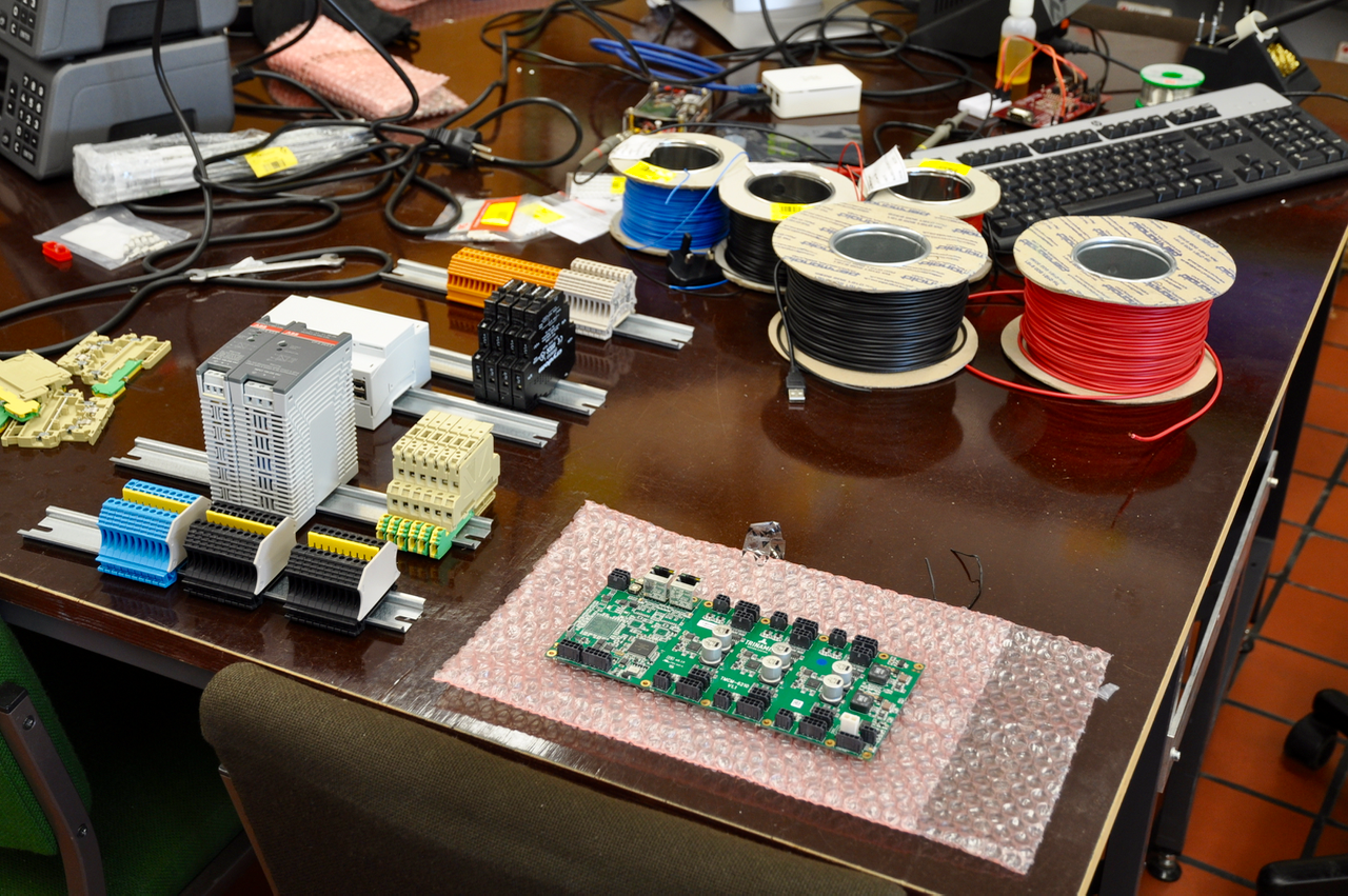
You might remember previous images of USAXS electronics, for example that one shown in Figure 1. We now needed to tidy all that up in a neat, shippable package. Fortunately, we’ve used DIN-rail-mountable components wherever we could, so we just needed a framework.
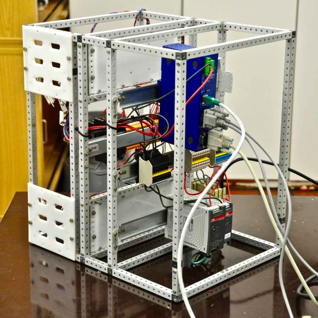
We found several wooden boxes from the 1980s, with a contemporary “rapid prototyping kit” in them, essentially a Meccano for adults. It has profiles, gears, linkages, chains, hinges, sliders, ball-bearings and axles, and was used for making quick rigs for testing and measuring. All components are made from (anodized) aluminium, and have survived time well. So we nicked that, and built, with a bit of help from my colleagues, the supporting framework for the electronics.

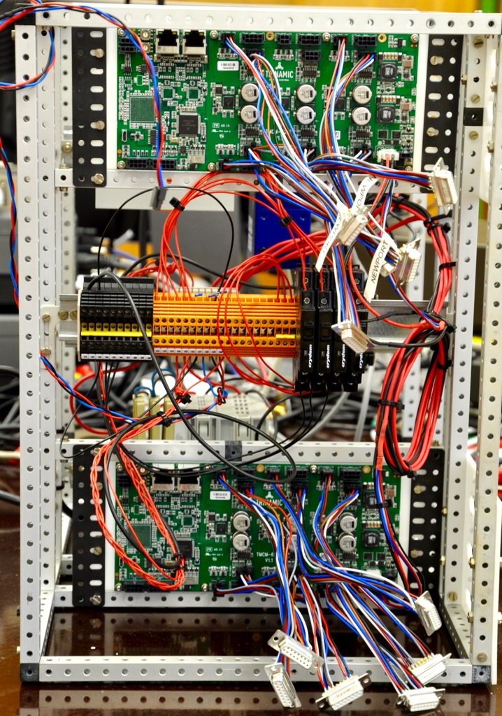
Figure 2 and 3 show two angles, one of the power supply and serial interface side, and the second of the motor controller side. I didn’t quite get as far as I wanted before the pictures were taken: the eleven motor connectors have not yet been mounted on the white laser-cut panels on the side.
Once that is done, I’ll have to try to fit the Raspberry Pi in. This Pi is controlling the instrument through python / jupyter notebooks. Most of the electronics can be reached over RS232 using the ethernet-to-RSXXX converter, but unfortunately there’s something amiss with the RS485 connection: I can’t get bidirectional communication going with the two motor controllers, something’s wrong with the signal levels. A temporary fix (nothing lasts as long…) is to use the USB connections, but it’s not nearly as neat.
The wiring isn’t quite so tidy yet, but I think that’ll improve once the connectors are on their panels. Some heavy tie-wrapping should also improve matters. So far, though: progress!
Leave a Reply