In this series of posts, we take a quick look at some uncommon corrections you can do to your scattering patterns and we evaluate whether they are worththe trouble or not. The goal is to arrive at intensities which are within 1% of their correct values.
In the previous post, we looked at the sample self-absorption behaviour. This turned out only to significantly affect the scattering patterns at very high absorptions and large scattering angles. Additionally, its complexity makes it difficult to implement for all types of samples (it was only derived for the simple case of a sheet-like sample, not for the more common capillary- or cylindrical shape). Thus, this correction should only be considered necessary to apply for highly absorbing samples scattering to angles above 5 degrees.
Two other corrections to consider are the polarization correction and the spherical correction. The spherical correction, correcting for the differences in angular coverage by the detector pixels, was also treated in the “how to do a perfect measurement”-document of a few posts ago. This is a straightforward correction requiring just some geometrical parameters, and correcting the small-angle scattering intensity to a few tens of percent. While not big, its simplicity means it is not worth neglecting.
The polarization correction is a correction whose magnitude depends on the degree and direction of polarization of the incident radiation and the direction of the scattered radiation. Even for unpolarized beams, the polarization correction has to be applied. While this correction is also detailed in the aforementioned document, no information on the magnitude of this correction was given.
We will consider two cases, one where the beam is highly polarized in the horizontal plane (95 % as commonly found at SAXS beamlines at synchrotrons), and the case where the incoming radiation is not polarized (as on your laboratory equipment).


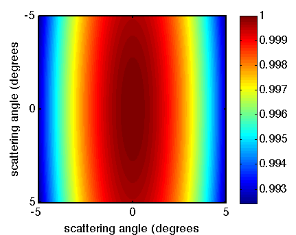
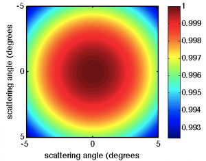
Implementing the equation as given in the aforementioned document, we arrive at the correction factors for the 95% polarization case shown in Figure 1 for up to 5 degrees scattering angle. While the scattering in the vertical direction does not need any significant correction, the horizontal scattering correction is in the tenths of percents. For unpolarized radiation, the correction factors are isotropic, again on the order of tenths of percents.
While these results show that the polarization factor correction is small, this (like the spherical correction) is a straightforward correction to implement, not requiring much effort. Therefore it should also be applied in the search for intensities accurate to 99%.
What should be apparent by now from these results, is that collecting (or rather correcting) a scattering pattern to much less than 1% error is quite a bit more difficult than trying to correct them to 1% error. But what do we gain from all these corrections? Read the next entry to find out what 1% error (or 99% accurate intensities) means for your results.

Leave a Reply